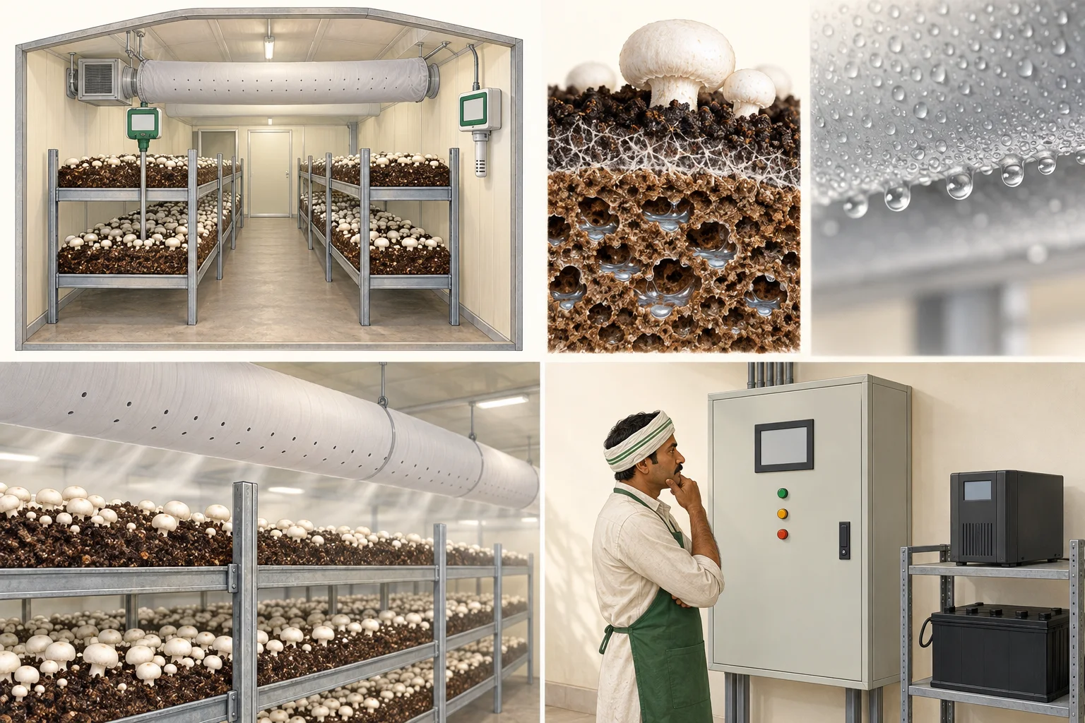


Quick orientation
Use this page to calculate assembly heat flow while keeping bridges, solar and infiltration separate.
Simple explanation
Envelope Transmission Load helps the grower calculate assembly heat flow while keeping bridges, solar and infiltration separate. The crop requirement is the starting question, not an equipment size.
Biological purpose
Engineering begins only after the crop stage, biological load and acceptable room response are declared.
Operator explanation
Observe the crop, room pattern and change history before changing a control. Record what changed, where, when and under which operating mode.
Engineering explanation
Define the control volume, design case, load components, equipment boundaries, instrumentation and expected response. Biological requirement is not equipment size.
What to observe
Look for spatial gradients, time trends, surface condition, crop response, door events, water events, equipment state and alarms rather than a single display value.
What to measure
Retain sensor ID, unit, location, height or depth, timestamp, calibration state, crop stage, room load and operating mode with every measurement.
Variables that interact
calculate assembly heat flow while keeping bridges, solar and infiltration separate. Temperature, moisture, carbon dioxide, air movement, crop load and control actions can move together, oppose one another or hide a local problem.
What can go wrong
Common errors include a non-representative sensor, an undefined design case, a fan rating treated as delivered airflow, an air-change rate treated as distribution, or a biological target treated as plant capacity.
What changes at commercial scale
Larger crop loads, longer air paths, more simultaneous equipment, tighter recovery needs and higher failure consequences increase the need for redundancy, commissioning and data history.
Reference and review boundary
Background/reference map: Farm Design for White Button Mushroom Cultivation; National Building Code of India 2016; 2025 ASHRAE Handbook Fundamentals table of contents; ISHRAE standards and position papers. This map supports further editorial work; it is not route-specific technical validation. Foundational, current, regulatory and engineering references retain their distinct roles, and manufacturer literature may only establish equipment-specific data.
Envelope transmission component
Uses Q = U × A × ΔT. Bridges, solar effects, doors and infiltration remain separate load components.
Complete all three non-negative inputs to calculate this component.
The numbers for this room, with their source.
Crop-climate values are published from ICAR-DMR guidance with the stage they apply to. Equipment sizes stay project-specific and are never published as defaults.
ENV.ROOM.U_VALUEpending technical verificationEnvelope U-value
Technical value pending verification- Unit
- W/(m²·K)
- Context
- Assembly-specific, not panel label alone
- Review needed from
- Qualified HVAC or electrical engineer
ENV.ROOM.INFILTRATIONpending technical verificationInfiltration air volume
Technical value pending verification- Unit
- m³/h
- Context
- Test or calculation method declared
- Review needed from
- Qualified HVAC or electrical engineer
ENV.LOAD.TRANSMISSIONpending technical verificationEnvelope transmission load
Technical value pending verification- Unit
- kW
- Context
- Area, U-value and design temperature difference retained
- Review needed from
- Qualified HVAC or electrical engineer
Transparent calculation framework
Equations expose variables, units, assumptions, validation and the point where project data must enter.
ENV.FORMULA.U_VALUERelate assembly resistance and transmittance
Required variables
- R_total · total assembly thermal resistance
- m²·K/W; includes all declared layers and surface films
Assumptions
- Area-weighted bridges are treated separately
- Layer data and installation condition are verified
Validation
- Resistance must be positive
- Higher resistance produces lower U-value
ENV.FORMULA.TRANSMISSIONCalculate steady envelope transmission heat flow
Required variables
- U · assembly thermal transmittance
- W/(m²·K); verified assembly value
- A · surface area
- m²; measured geometry
- ΔT · design temperature difference
- K; declared design case
Assumptions
- Steady one-dimensional heat flow
- Thermal bridges, solar effects and infiltration are separate
Validation
- Zero area returns zero
- Doubling area doubles heat flow
ENV.FORMULA.DEMANDStructure a coincident electrical demand schedule
Required variables
- P_running,i · equipment running input
- kW; nameplate or measured input
- coincidence_i · scenario coincidence
- ratio; documented operating sequence
Assumptions
- Starting transient is evaluated separately
- Power factor and kVA are not inferred from kW
Validation
- Coincidence factors are between zero and one
- Every included load has a declared scenario
Evidence and review
Source type, applicability and limitations stay visible so older farm guidance is not mistaken for current engineering law.
foundational · buildingFarm Design for White Button Mushroom Cultivation
Indian production-room workflow, farm components, controlled-room and air-handling context.
Foundational farm guidance does not replace current structural, refrigeration, electrical or safety design.
Open primary sourcecurrent · buildingNational Building Code of India 2016
Building, fire, services, refrigeration, sanitation, electrical and facility-management context.
Local adoption, amendments, authority requirements and specialist codes must be verified for each project.
Open primary sourcecurrent · hvac2025 ASHRAE Handbook Fundamentals table of contents
Current chapter architecture for psychrometrics, refrigeration cycles, heat transfer, controls and measurement.
The public index identifies the current edition; detailed design use requires access to the handbook.
Open primary sourcecurrent · hvacISHRAE standards and position papers
Indian HVAC standards context including air-handling units and commissioning.
Standard titles are an index; design claims must cite and comply with the applicable edition and project jurisdiction.
Open primary source