


A practical guide to growing mushrooms in IndiaA joint educational initiative by MushroomWale & DMR Solan
MushroomFarming.in

A joint educational initiative by

MushroomWale.com
ICAR–Directorate of Mushroom Research, Solan logoICAR–DMRSolan

MushroomFarming / guide

Cooling System Architecture

A governed engineering guide to connect room loads, air states, refrigeration capacity, redundancy, controls and heat rejection.

Practical explanation + detailed referenceSources & review ↓
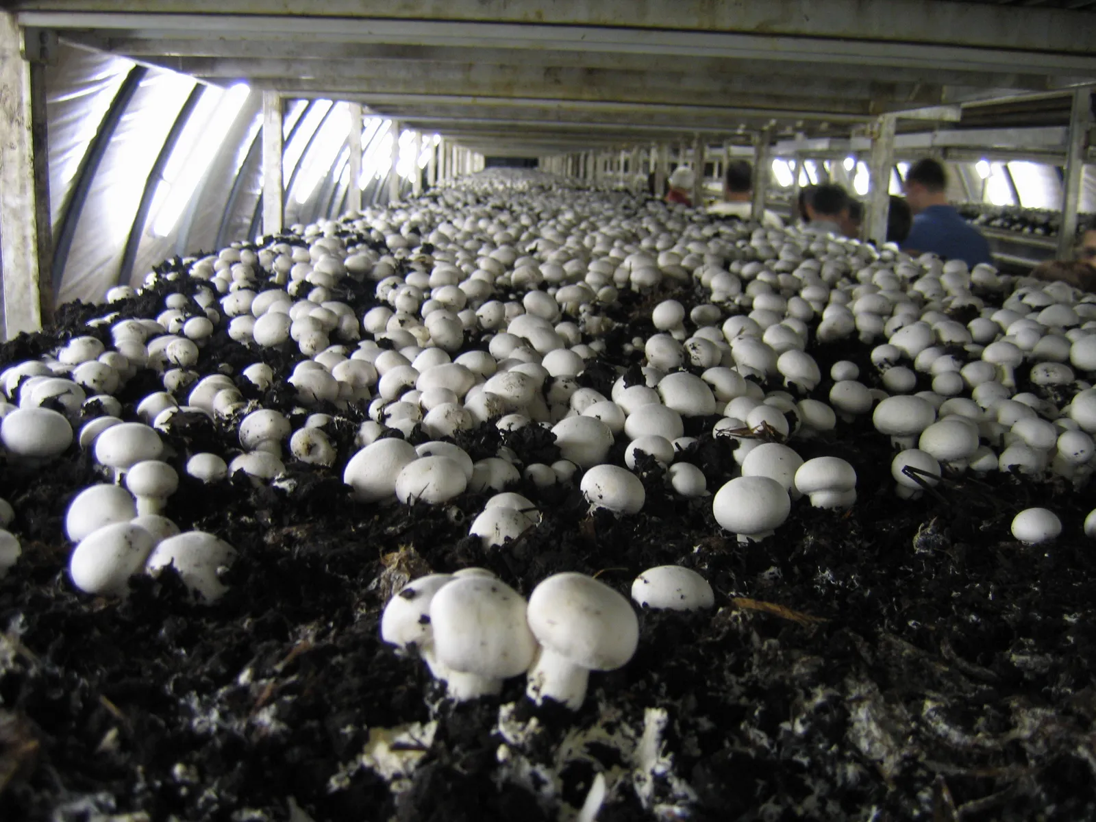
White button mushrooms on casing soil in long shelf beds inside a commercial cropping room near Eger, Hungary.
Real cultivation photograph. Read its source for location and context; it is not a universal operating specification.Andrew Bossi · CC BY-SA 2.5View full photograph ↗
On this pageChoose a section, or keep reading below

Read this in the full guide: Read the room and make a controlled adjustment

Understand the topic

Start with the explanation.

Use this page to connect room loads, air states, refrigeration capacity, redundancy, controls and heat rejection.

Part 01

Simple explanation

Cooling System Architecture helps the grower connect room loads, air states, refrigeration capacity, redundancy, controls and heat rejection. The crop requirement is the starting question, not an equipment size.

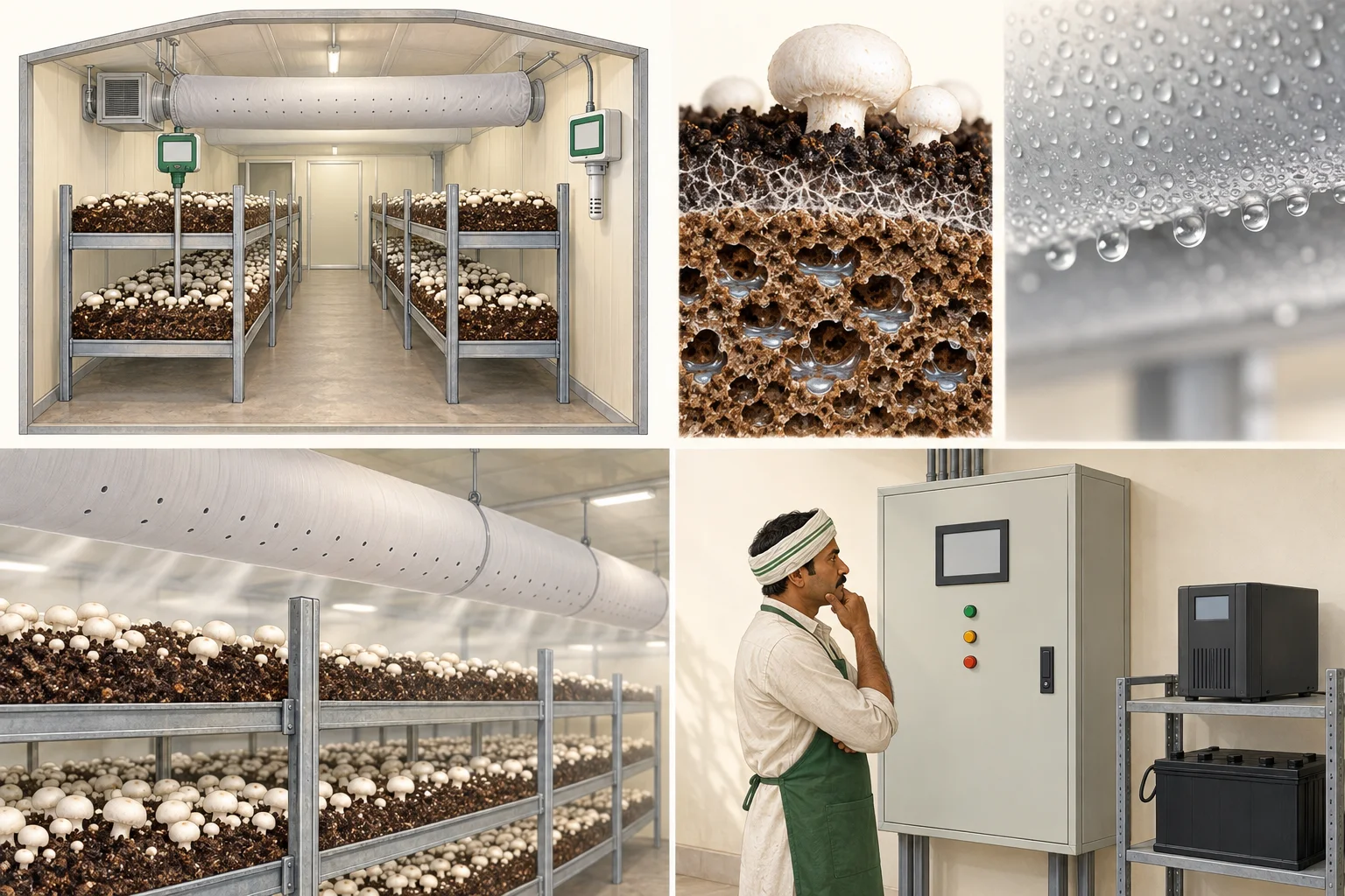
Educational grow-room illustration showing separate crop and room measurement locations.
AI teaching illustrationAir versus bed

Air and growing material are different measurement locations. An active crop releases heat; the wall display is not every bed's temperature.

Conceptual explanation—not a real farm photograph, diagnostic finding or construction specification.
Part 02

Biological purpose

Engineering begins only after the crop stage, biological load and acceptable room response are declared.

Part 03

Operator explanation

Observe the crop, room pattern and change history before changing a control. Record what changed, where, when and under which operating mode.

Part 04

Engineering explanation

Define the control volume, design case, load components, equipment boundaries, instrumentation and expected response. Biological requirement is not equipment size.

Part 05

What to look for

Look for spatial gradients, time trends, surface condition, crop response, door events, water events, equipment state and alarms rather than a single display value.

Part 06

What to measure

Retain sensor ID, unit, location, height or depth, timestamp, calibration state, crop stage, room load and operating mode with every measurement.

Part 07

Variables that interact

connect room loads, air states, refrigeration capacity, redundancy, controls and heat rejection. Temperature, moisture, carbon dioxide, air movement, crop load and control actions can move together, oppose one another or hide a local problem.

Part 08

What can go wrong

Common errors include a non-representative sensor, an undefined design case, a fan rating treated as delivered airflow, an air-change rate treated as distribution, or a biological target treated as plant capacity.

Part 09

What changes at commercial scale

Larger crop loads, longer air paths, more simultaneous equipment, tighter recovery needs and higher failure consequences increase the need for redundancy, commissioning and data history.

Part 10

Reference and review boundary

Background/reference map: 2025 ASHRAE Handbook Fundamentals table of contents; ISHRAE HVAC Databook 2025; India Cooling Action Plan. This map supports further editorial work; it is not route-specific technical validation. Foundational, current, regulatory and engineering references retain their distinct roles, and manufacturer literature may only establish equipment-specific data.

Illustration of a responsible operator inspecting a closed control cabinet.
AI teaching illustrationPrepare for failure

Controls, alarms and operator response work as a system. An alarm only helps when someone knows what to do next.

Conceptual explanation—not a real farm photograph, diagnostic finding or construction specification.

Go deeper

Technical reference, records and tools.

Detailed crop-stage information, parameters, diagrams and specialist tools are kept together below. This material retains its source conditions and review limits.

Open the complete technical reference

engineering · engineering guide

Cooling System Architecture

A governed engineering guide to connect room loads, air states, refrigeration capacity, redundancy, controls and heat rejection.

Crop context
Agaricus bisporus
Publication
Editorial review in progress
External review
Not yet recorded · needed from Qualified HVAC, refrigeration or electrical reviewer
Evidence records
3
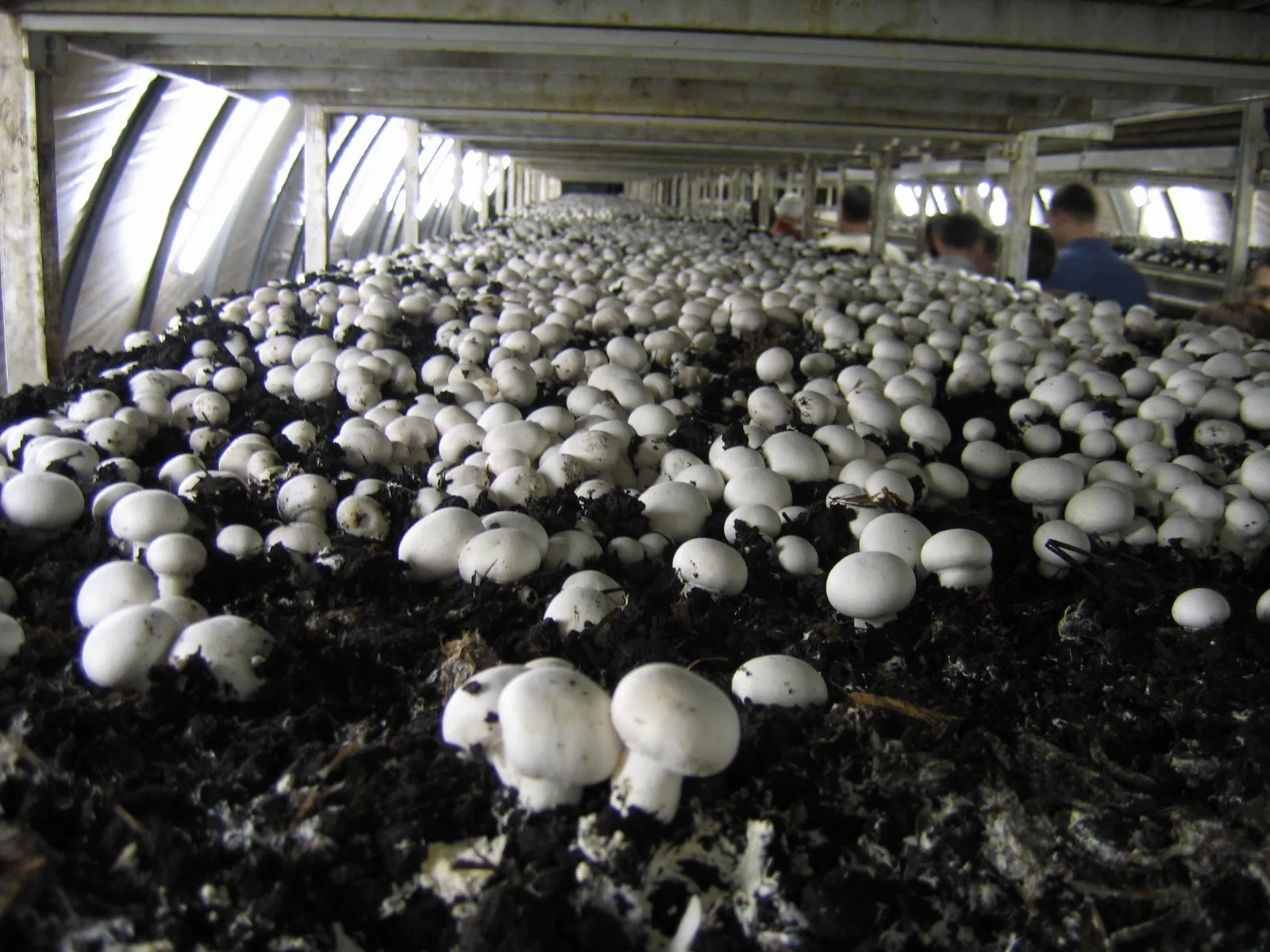
White button mushrooms on casing soil in long shelf beds inside a commercial cropping room near Eger, Hungary.
Button mushrooms on casing in long shelf beds inside a grow room (Hungary). Photo: Andrew Bossi, CC BY-SA 2.5. Source

Controlled room: how the air moves

Cooled, humid air drops from the overhead duct onto the beds, returns through the room, and 20 to 30 percent fresh air is mixed in. About 15 cm per second over the beds, 4 to 6 air changes an hour. Source: ICAR-DMR manual.

Perforated supply ductAHUcooling coilhumidifierreturnfresh air 20-30%
Supply airReturn airBeds
Picture → explanation → field task

Understand the working room

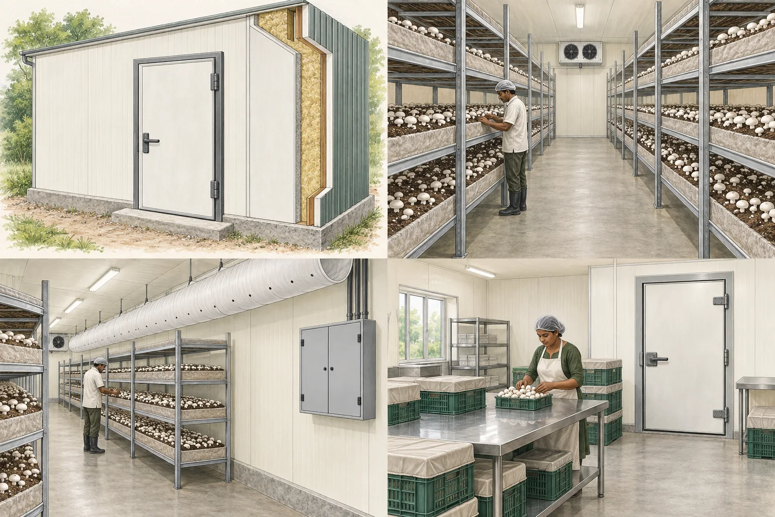
AI-generated educational illustrations. Not actual farm photographs, diagnostic evidence or construction specifications.

Generated illustration of mushroom racks with a central access aisle and a worker.
02

Leave room for people to work

People need access to every growing level. Adding shelf area changes handling, access and air distribution. An attractive room picture cannot establish safe rack dimensions.

Try this on your farm

Walk through loading, harvesting, cleaning and emergency access with the designer before fixing the rack arrangement.

Generated illustration of an overhead fabric air-distribution duct and a closed control cabinet.
03

Distribute air through the crop

The duct serves a room containing racks and crop. Air delivery must be evaluated in the loaded room. Equipment capacity alone does not demonstrate uniform crop conditions.

Try this on your farm

Include representative loaded-room measurements, maintenance access and alarm checks in commissioning. Keep electrical cabinets closed.

Quick orientation

Use this page to connect room loads, air states, refrigeration capacity, redundancy, controls and heat rejection.

01

Simple explanation

Cooling System Architecture helps the grower connect room loads, air states, refrigeration capacity, redundancy, controls and heat rejection. The crop requirement is the starting question, not an equipment size.

02

Biological purpose

Engineering begins only after the crop stage, biological load and acceptable room response are declared.

03

Operator explanation

Observe the crop, room pattern and change history before changing a control. Record what changed, where, when and under which operating mode.

04

Engineering explanation

Define the control volume, design case, load components, equipment boundaries, instrumentation and expected response. Biological requirement is not equipment size.

05

What to observe

Look for spatial gradients, time trends, surface condition, crop response, door events, water events, equipment state and alarms rather than a single display value.

06

What to measure

Retain sensor ID, unit, location, height or depth, timestamp, calibration state, crop stage, room load and operating mode with every measurement.

07

Variables that interact

connect room loads, air states, refrigeration capacity, redundancy, controls and heat rejection. Temperature, moisture, carbon dioxide, air movement, crop load and control actions can move together, oppose one another or hide a local problem.

08

What can go wrong

Common errors include a non-representative sensor, an undefined design case, a fan rating treated as delivered airflow, an air-change rate treated as distribution, or a biological target treated as plant capacity.

09

What changes at commercial scale

Larger crop loads, longer air paths, more simultaneous equipment, tighter recovery needs and higher failure consequences increase the need for redundancy, commissioning and data history.

10

Reference and review boundary

Background/reference map: 2025 ASHRAE Handbook Fundamentals table of contents; ISHRAE HVAC Databook 2025; India Cooling Action Plan. This map supports further editorial work; it is not route-specific technical validation. Foundational, current, regulatory and engineering references retain their distinct roles, and manufacturer literature may only establish equipment-specific data.

The numbers for this room, with their source.

Crop-climate values are published from ICAR-DMR guidance with the stage they apply to. Equipment sizes stay project-specific and are never published as defaults.

ENV.REFRIGERATION.CAPACITYpending technical verification

Refrigeration capacity

Technical value pending verification
Unit
kW refrigeration
Context
Evaporating, condensing and part-load conditions retained
Review needed from
Qualified HVAC or electrical engineer
ENV.REFRIGERATION.COPpending technical verification

Coefficient of performance

Technical value pending verification
Unit
dimensionless
Context
Cooling output and electrical input boundary matched
Review needed from
Qualified HVAC or electrical engineer
ENV.AHU.COIL_DUTYpending technical verification

Cooling-coil duty

Technical value pending verification
Unit
kW
Context
Air states, flow, fluid conditions and fouling basis retained
Review needed from
Qualified HVAC or electrical engineer

Transparent calculation framework

Equations expose variables, units, assumptions, validation and the point where project data must enter.

ENV.FORMULA.COP

Relate refrigeration output to electrical input at one condition

COP = Q_cooling ÷ P_input

Required variables

Q_cooling · useful cooling output
kW; same rating and boundary as input
P_input · electrical input
kW; compressor or system boundary stated

Assumptions

  • Steady declared operating point
  • Auxiliaries are included only if stated

Validation

  • Input power must be positive
  • Output and input units cancel

Evidence and review

Source type, applicability and limitations stay visible so older farm guidance is not mistaken for current engineering law.

current · hvac2025 ASHRAE Handbook Fundamentals table of contents

Current chapter architecture for psychrometrics, refrigeration cycles, heat transfer, controls and measurement.

The public index identifies the current edition; detailed design use requires access to the handbook.

Open primary source
current · hvacISHRAE HVAC Databook 2025

Current Indian HVAC design-data reference architecture.

The public product record is not evidence for a numeric design value; use the licensed text and record edition and page.

Open primary source
current · refrigerationIndia Cooling Action Plan

Indian refrigerant transition, energy-efficiency and low-GWP cooling policy context.

Refrigerant selection also depends on current law, safety classification, equipment certification, servicing ecosystem and project constraints.

Open primary source

Read the evidence

Sources & review.

Editorial update: 2026-08-23. Independent technical review is not recorded for this entry.

  1. 2025 ASHRAE Handbook Fundamentals table of contents

    ASHRAE

  2. ISHRAE HVAC Databook 2025

    ISHRAE

  3. India Cooling Action Plan

    MoEFCC Ozone Cell

Reading a source is not the same as applying its instructions to every farm. Confirm species, strain, crop stage, system, region and publication date. Old chemical recommendations are not current-use instructions.

See something that needs correcting? Tell us →