


A practical guide to growing mushrooms in IndiaA joint educational initiative by MushroomWale & DMR Solan
MushroomFarming.in

A joint educational initiative by

MushroomWale.com
ICAR–Directorate of Mushroom Research, Solan logoICAR–DMRSolan

MushroomFarming / guide

Sensor Architecture

A governed engineering guide to assign each sensor a question, location, range, accuracy, maintenance and redundancy role.

Practical explanation + detailed referenceSources & review ↓
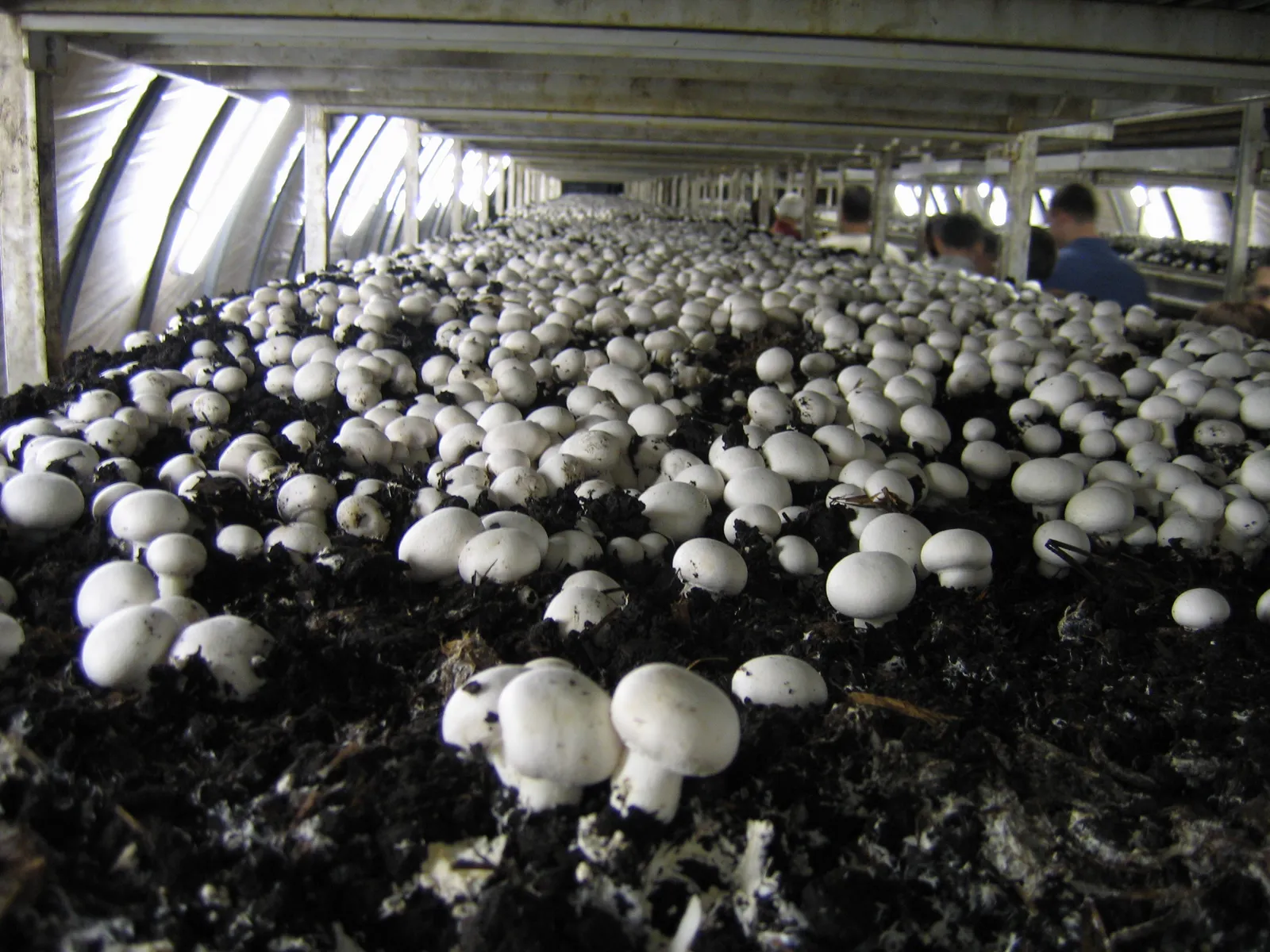
White button mushrooms on casing soil in long shelf beds inside a commercial cropping room near Eger, Hungary.
Real cultivation photograph. Read its source for location and context; it is not a universal operating specification.Andrew Bossi · CC BY-SA 2.5View full photograph ↗
On this pageChoose a section, or keep reading below

Read this in the full guide: Read the room and make a controlled adjustment

Understand the topic

Start with the explanation.

Use this page to assign each sensor a question, location, range, accuracy, maintenance and redundancy role.

Part 01

Simple explanation

Sensor Architecture helps the grower assign each sensor a question, location, range, accuracy, maintenance and redundancy role. The crop requirement is the starting question, not an equipment size.

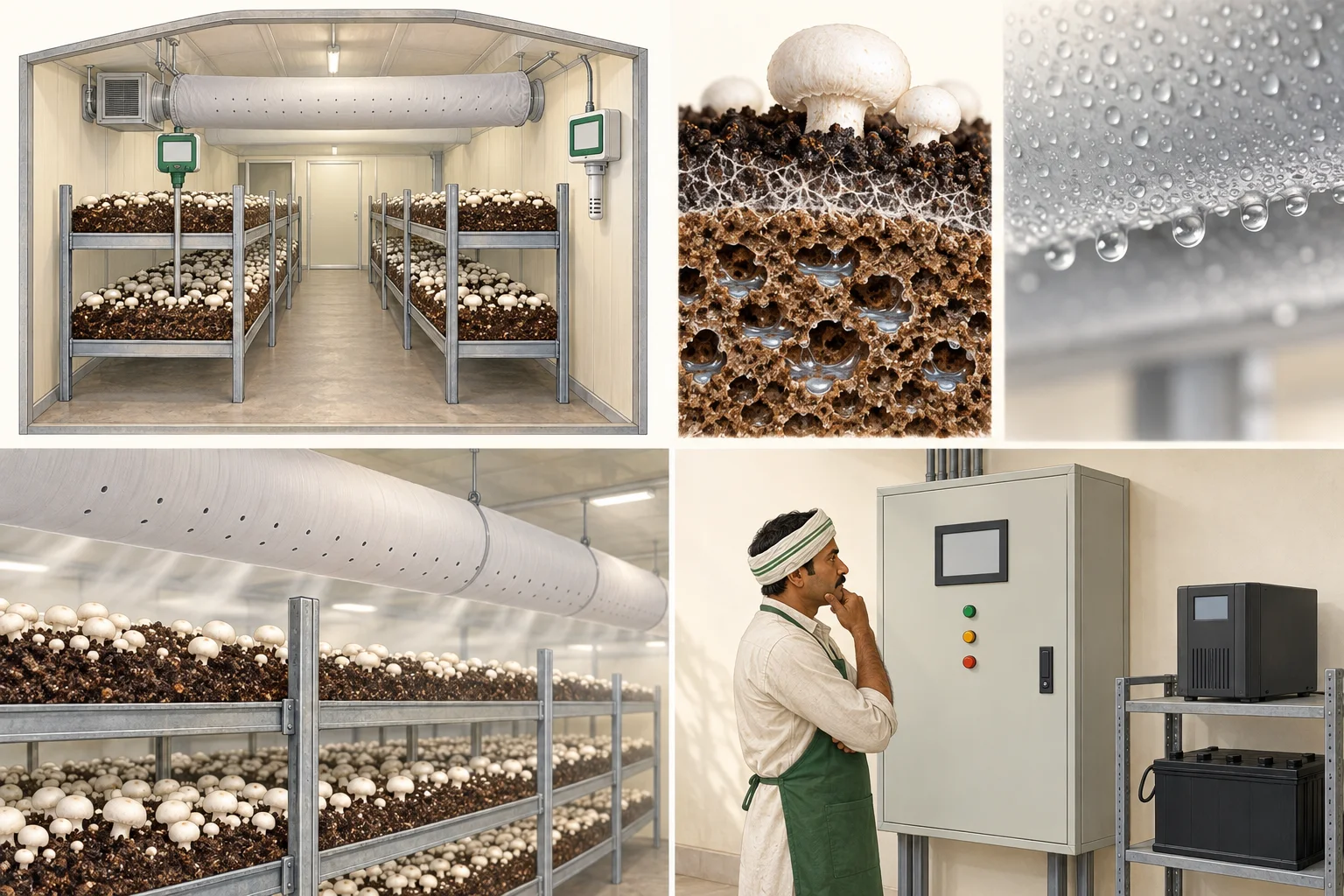
Educational grow-room illustration showing separate crop and room measurement locations.
AI teaching illustrationAir versus bed

Air and growing material are different measurement locations. An active crop releases heat; the wall display is not every bed's temperature.

Conceptual explanation—not a real farm photograph, diagnostic finding or construction specification.
Part 02

Biological purpose

Engineering begins only after the crop stage, biological load and acceptable room response are declared.

Part 03

Operator explanation

Observe the crop, room pattern and change history before changing a control. Record what changed, where, when and under which operating mode.

Part 04

Engineering explanation

Define the control volume, design case, load components, equipment boundaries, instrumentation and expected response. Biological requirement is not equipment size.

Part 05

What to look for

Look for spatial gradients, time trends, surface condition, crop response, door events, water events, equipment state and alarms rather than a single display value.

Part 06

What to measure

Retain sensor ID, unit, location, height or depth, timestamp, calibration state, crop stage, room load and operating mode with every measurement.

Part 07

Variables that interact

assign each sensor a question, location, range, accuracy, maintenance and redundancy role. Temperature, moisture, carbon dioxide, air movement, crop load and control actions can move together, oppose one another or hide a local problem.

Part 08

What can go wrong

Common errors include a non-representative sensor, an undefined design case, a fan rating treated as delivered airflow, an air-change rate treated as distribution, or a biological target treated as plant capacity.

Part 09

What changes at commercial scale

Larger crop loads, longer air paths, more simultaneous equipment, tighter recovery needs and higher failure consequences increase the need for redundancy, commissioning and data history.

Part 10

Reference and review boundary

Background/reference map: AMCA Publication 201-23: Fans and Systems; Improving Fan System Performance: A Sourcebook for Industry; ISHRAE standards and position papers; ASHRAE Handbook Fundamentals, Chapter 1: Psychrometrics. This map supports further editorial work; it is not route-specific technical validation. Foundational, current, regulatory and engineering references retain their distinct roles, and manufacturer literature may only establish equipment-specific data.

Illustration of a responsible operator inspecting a closed control cabinet.
AI teaching illustrationPrepare for failure

Controls, alarms and operator response work as a system. An alarm only helps when someone knows what to do next.

Conceptual explanation—not a real farm photograph, diagnostic finding or construction specification.

Go deeper

Technical reference, records and tools.

Detailed crop-stage information, parameters, diagrams and specialist tools are kept together below. This material retains its source conditions and review limits.

Open the complete technical reference

engineering · engineering guide

Sensor Architecture

A governed engineering guide to assign each sensor a question, location, range, accuracy, maintenance and redundancy role.

Crop context
Agaricus bisporus
Publication
Editorial review in progress
External review
Not yet recorded · needed from Qualified HVAC, refrigeration or electrical reviewer
Evidence records
4
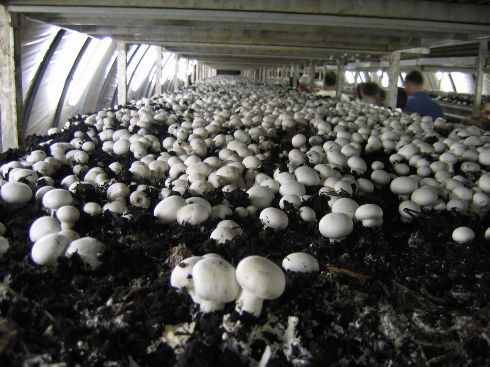
White button mushrooms on casing soil in long shelf beds inside a commercial cropping room near Eger, Hungary.
Button mushrooms on casing in long shelf beds inside a grow room (Hungary). Photo: Andrew Bossi, CC BY-SA 2.5. Source

Controlled room: how the air moves

Cooled, humid air drops from the overhead duct onto the beds, returns through the room, and 20 to 30 percent fresh air is mixed in. About 15 cm per second over the beds, 4 to 6 air changes an hour. Source: ICAR-DMR manual.

Perforated supply ductAHUcooling coilhumidifierreturnfresh air 20-30%
Supply airReturn airBeds
Picture → explanation → field task

A crop-room round

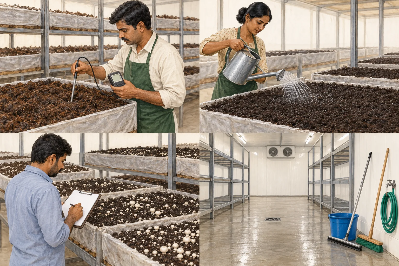
AI-generated educational illustrations. Not actual farm photographs, diagnostic evidence or construction specifications.

Generated illustration of an operator inserting a temperature probe into a compost bed.
01

Measure the bed, not only the air

The probe measures growing material at a specific location. Room air and biologically active compost can have different temperatures. One reading is not a whole-room survey.

Try this on your farm

Use a consistent measurement location and method. Record time, crop stage and bed position with the value.

Generated illustration of a grower recording different pin densities along mushroom beds.
03

Compare the pinning pattern

The bed does not develop uniformly at every position. Differences can involve inputs, water or room conditions. A patch is an observation, not a diagnosis.

Try this on your farm

Compare fixed locations over successive rounds. Photograph the same patch and record nearby readings before changing settings.

Quick orientation

Use this page to assign each sensor a question, location, range, accuracy, maintenance and redundancy role.

01

Simple explanation

Sensor Architecture helps the grower assign each sensor a question, location, range, accuracy, maintenance and redundancy role. The crop requirement is the starting question, not an equipment size.

02

Biological purpose

Engineering begins only after the crop stage, biological load and acceptable room response are declared.

03

Operator explanation

Observe the crop, room pattern and change history before changing a control. Record what changed, where, when and under which operating mode.

04

Engineering explanation

Define the control volume, design case, load components, equipment boundaries, instrumentation and expected response. Biological requirement is not equipment size.

05

What to observe

Look for spatial gradients, time trends, surface condition, crop response, door events, water events, equipment state and alarms rather than a single display value.

06

What to measure

Retain sensor ID, unit, location, height or depth, timestamp, calibration state, crop stage, room load and operating mode with every measurement.

07

Variables that interact

assign each sensor a question, location, range, accuracy, maintenance and redundancy role. Temperature, moisture, carbon dioxide, air movement, crop load and control actions can move together, oppose one another or hide a local problem.

08

What can go wrong

Common errors include a non-representative sensor, an undefined design case, a fan rating treated as delivered airflow, an air-change rate treated as distribution, or a biological target treated as plant capacity.

09

What changes at commercial scale

Larger crop loads, longer air paths, more simultaneous equipment, tighter recovery needs and higher failure consequences increase the need for redundancy, commissioning and data history.

10

Reference and review boundary

Background/reference map: AMCA Publication 201-23: Fans and Systems; Improving Fan System Performance: A Sourcebook for Industry; ISHRAE standards and position papers; ASHRAE Handbook Fundamentals, Chapter 1: Psychrometrics. This map supports further editorial work; it is not route-specific technical validation. Foundational, current, regulatory and engineering references retain their distinct roles, and manufacturer literature may only establish equipment-specific data.

Sensor architecture library

A sensor is a measurement system with a location, purpose, verification method and failure history.

SENSOR-AIR-TEMP-RH

Air dry bulb and relative humidity

Does the point represent crop air rather than a wall, coil discharge or door plume?

Installation
Shield from radiant and wetting bias; Record height, rack, aisle and air path; Allow service access
Verification
Compare against a traceable reference; Verify time alignment and logging interval; Inspect drift after wet cleaning
Failure modes
Condensation on element; wall temperature bias; unrecorded replacement
SENSOR-COMPOST-TEMP

Compost temperature

Are depth, bed position, rack level and insertion contact repeatable?

Installation
Define insertion depth; Map representative beds; Protect cable and connector
Verification
Cross-check probes; Record point identity; Review response time
Failure modes
shallow insertion; poor contact; single-point overconfidence
SENSOR-CO2

Carbon-dioxide concentration

Can the placement reveal gradients rather than only return-air average?

Installation
Record height and air path; Avoid direct fresh-air jet; Provide calibration access
Verification
Zero/span method per instrument; Compare map points; Review pressure and cross-sensitivity limits
Failure modes
drift; condensation; blocked sample line; false representativeness
SENSOR-PRESSURE

Differential pressure

Are the reference zones, tube routes and door states defined?

Installation
Label high and low ports; Protect tubes from water; Locate reference away from local jets
Verification
Zero check; leak check; door-state test
Failure modes
reversed tubes; water in line; undefined reference
SENSOR-AIR-VELOCITY

Air speed and direction

Is the instrument suitable for low-speed, directional mapping among racks?

Installation
Define orientation; use repeatable grid; record occupied crop state
Verification
instrument zero and calibration; repeat traverse; compare supply and return balance
Failure modes
orientation error; operator blockage; snapshot treated as permanent

Printable field sheets

Download a blank CSV, open it in a spreadsheet, and record the actual observations with units and references. These educational templates are not acceptance criteria or engineering certificates.

Evidence and review

Source type, applicability and limitations stay visible so older farm guidance is not mistaken for current engineering law.

current · airflowAMCA Publication 201-23: Fans and Systems

Fan ratings, installed-system effects and the relationship between fan and system curves.

The standard does not supply a mushroom-room duty point or distribution result.

Open primary source
foundational · airflowImproving Fan System Performance: A Sourcebook for Industry

System curves, fan components, resistance, control and performance verification.

General fan engineering requires project measurements and a qualified designer for final selection.

Open primary source
current · hvacISHRAE standards and position papers

Indian HVAC standards context including air-handling units and commissioning.

Standard titles are an index; design claims must cite and comply with the applicable edition and project jurisdiction.

Open primary source
foundational · psychrometricsASHRAE Handbook Fundamentals, Chapter 1: Psychrometrics

Moist-air properties, psychrometric relationships, measurement and process calculations in SI units.

Equations describe air properties; they do not determine a crop target or equipment selection by themselves.

Open primary source

Read the evidence

Sources & review.

Editorial update: 2026-08-23. Independent technical review is not recorded for this entry.

  1. AMCA Publication 201-23: Fans and Systems

    AMCA International

  2. Improving Fan System Performance: A Sourcebook for Industry

    United States Department of Energy

  3. ISHRAE standards and position papers

    ISHRAE

  4. ASHRAE Handbook Fundamentals, Chapter 1: Psychrometrics

    ASHRAE

Reading a source is not the same as applying its instructions to every farm. Confirm species, strain, crop stage, system, region and publication date. Old chemical recommendations are not current-use instructions.

See something that needs correcting? Tell us →